Critical embedded systems

POWER SUBSTATION AUTOMATION

Designed to meet the requirements of the EN61850 standard, the ACS range is used to control and manage the power supply of electrical substations.

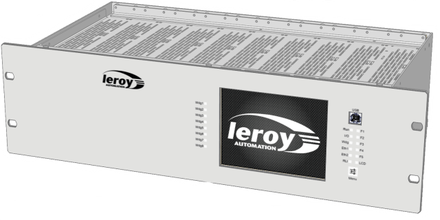
The touch screen on the front panel allows ergonomic control of the installation: visualize, order, list and acknowledge defects, …

The inputs / outputs are wired on the rear panel. They are designed to adapt to any type of power supply : 24Vdc, 48Vdc or 125Vdc.

The IEC61850 protocol allows an integration into the global control system of the substation.

More than 30000 ACS modular boards are installed to date.

MAIN FEATURES

5.7″ display – Console socket – Diagnostic LEDs

8 input/output cards per rack

  • Central processing processor :
    • Marvel Xscale 32 bits 416Mhz
  • I/O coprocessor :
    • STM32 120Mhz
  • Memories :
    • RAM : 64Mo
    • Flash ROM : 32Mo
    • Flash (persistent memory)  : 4Ko
  • Rack 3U 19″. 
  • IP 30
  • Dimensions :W x H x D = (N x 132) x 482 x 217 mm
  • Wiring of inputs/outputs and communication on the rear panel
  • Full range power supply : 38Vdc-144Vdc or 16Vdc-38Vdc
  • Consumption : <65W
  • Protection against overvoltages, overcurrents and short-circuits
  • Alarm relay closed if ACS is  powered off, in a reset phase or in faulty state.
  • Size : 5.7″ QVGA format 4:3. 131×100 mm
  • Resistive touchscreen : Type TFT LCD 320 x 240 pixels
  • Local setting
  • Process monitoring
  • List and acknowledgement of defects
  • USB connection type B female
  • Channel to the Straton’s programming workbench
  • Used as Modbus RTU serial link or serial protocol
  • Programming can be done via an Ethernet port
  • 2 ports Ethernet RJ45 100 Mbits/s 
  • 1 port FIP
    • EN 50170-3 Device manager – Bus arbitrator
    • Full Fip2, Private Ram : 512 Ko
  • 2 serial links RS232/RS485  up to 115200 bit/s
  • 1 modem port
  •  Protocols :
    • IEC 61850, IEC 61870
    • HNZ, FIP
  • LED diagnosis
  • Central unit status : RUN, WDG
  • Communication port status : ETH1, ETH2, FIP, RS
  • Inputs/Outputs card surveillance : local WDG
  • Software application status : LED driven by the software
  • Languages  IEC61131-3:
    • Ladder (LD)
    • Grafcet (SFC)
    • Structured text (ST)
    • Instruction List (IL)
    • Fanction Block Diagram (FBD)
  • Workbench : STRATON from CopaData

INPUTS/OUTPUTS FEATURES

Redundant Multi-voltage Inputs board

  • Board with 16 inputs
  • 2 distinct acquisition chains by input
  • Connector screw : 1 common for 2 inputs
  • Operating voltage of  each input : choice by wiring :
    • 24Vdc – 20 mA
    • 48Vdc – 15 mA
    • 125Vdc – 6 mA
  • Self-monitoring on the card:
    • Monitoring of internal tensions
    • Monitoring of the dialogue with the CPU
    • Redundancy of the card addressing on the bus

Control-command board

  • Board with 4 switchgear interfaces.
  • For each interface :
    • 1 relay output “to close the switchgear” 
    • 1 relay output  “to open the switchgear”
      • Max. switching voltage : 300Vdc
      • Max. switching power : 60W
    • 1 input “switchgear closed”
    • 1 input “switchgear open”
      • Choice of input voltage by wiring

ENVIRONMENTAL QUALIFICATION TESTS (IEC61850-3)

  • Operating temperature : -20°C/+70°C
  • Vibrations EN61850-3 : 20m/s²
  • Voltage dips and short interruptions : 20ms
EMC TESTS 
  • EN61000-4-2 Electric Static Discharge : ±8 kV (enclosure air)
  • EN61000-4-3 Radiated electromagnetic field immunity  : 80-3000 MHz  10V/m
  • EN61000-4-4 Fast transient/burst immunity  : ±4 kV
  • EN61000-4-5 Surge immunity  :
    • 4 kV (Common Mode)
    • 2 kV (Differential Mode)
  • EN61000-4-6 Conducted mode disturbances immunity  : 0.15-80 MHz 10Vrms

DOUBLE RTU CONFIGURATION

The Double RTU is a configuration that contains 2 independent central units in the same rack.
One of the central units can control inputs/outputs.