CANopen Master Redundancy for TCMS
CANopen Master Redundancy for TCMS
Train Control & Monitoring System (TCMS) in Railway Applications
This technical article discusses how to implement CANopen Master communication protocol with redundancy features in on-board Train Control and Management Systems (TCMS). In more details, it aims at demonstrating the benefits of using both CAN networks; CANopen protocol and redundancy architecture to address a high level of availability and safety needed in control/command applications such as TCMS (Train Control Monitoring System) architectures.
The advantages of CAN and CANopen protocols in an embedded system
In all control/command systems, communication between the controller and the actuators and sensors is a key element in the success of a project. Alongside Ethernet, CAN (Controller Area Network) technologies, initially produced to meet the requirements of the automotive market, and the high-level CANopen protocols have proven their robustness and reliability for a low implementation cost and a low consumption, allowing a multitude of possibilities, whatever the areas of application.
CAN Vs RS Serial Links
Unlike historical buses and protocols based on RS232, or RS422/485 such as Modbus RTU and PROFIBUS, or even MVB, CAN is a bus which allows messages to be prioritized without altering or destroying the message sent. Indeed, RS232 and RS422/485 serial buses allow Master/Slave polling type protocols, where the Master “speaks” and the Slaves “listen” by responding each one at a time… This method, also called “polling”, requires a cycle whose duration depends on the number of slaves and the quantity of information to be transmitted.

Master/Slave polling principle
On the contrary, CAN allows communication according to the Producer/Consumer model, where each node, whether master or slave, can speak whenever it wants, without worrying about the state of the bus.
This method achieves much better performance because message collisions are taken care of by the CAN controller and thus greatly facilitates the developer’s work.

Producer/Consumer model principle
CAN integrates layer 2 of the OSI model (data link layer), which is not the case for RS232 and RS422/485, which are limited to layer 1 (physical layer). In fact, RS485 is not a protocol because no frame definition exists at this level, unlike CAN. It only provides the basic rules and physical link for byte exchange to enable transmission of serial messages using a multipoint bus. The content of the message (the bits on the bus) is completely user defined. This is an advantage in terms of simplicity, but when it comes to compatibility, it becomes a disadvantage given the multitude of existing protocols.
The CANopen protocol
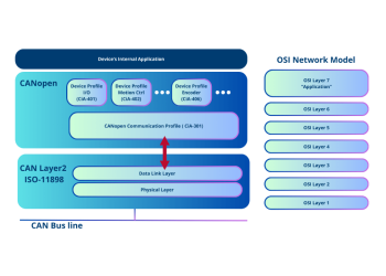
CANopen is a high-level application layer (layer 7 of the OSI model) which implements the mechanisms necessary for monitoring a network, periodic (PDO) and non-periodic (SDO) messages. CANopen thus authorizes Master/Slave type communications but also Producer/Consumer type communications, all simultaneously!
With asynchronous RS232/422/485 type links, the designer will have to write a “proprietary” protocol, which requires significant time for definition and implementation, with support for each node of the bus. The development may take a significant time and the reliability and robustness of a proprietary protocol could be uncertain!

PDO message example
The Object Dictionary
A fundamental notion of CANopen is the object dictionary. This dictionary is used to inform a CANopen supervisor (or Master) about the properties of a device, in a standardized manner. This mechanism thus allows this device to be modeled, in order to make the hardware independent of the control software. The benefit for the end user is to be able to choose their equipment independently of the manufacturer.
In order to facilitate this approach, significant work has been carried out by the non-profit organization CiA (CAN in Automation) through standards for business profiles: generic I/O modules (CiA 401), motion control and motors ( CiA 402), profile for IEC 61131-3 for industrial automation (CiA 405), medical devices (CiA 412), control systems for elevators (CiA 417), photovoltaic systems and wind turbines (CiA 437, CiA 406, etc.), battery charging systems – BMS – (CiA 418/419), municipal vehicles (CiA 422) and … Railway market too !

OSI and CANopen reference model
CANopen and the railway market
◆ CiA 421: CANopen application profile for train vehicle control networks
◆ CiA 423: CANopen application profile for rail vehicle power drive systems
◆ CiA 424: CANopen application profile for rail vehicle door control systems
◆ CiA 426: CANopen application profile for rail vehicle exterior lighting control
◆ CiA 430: CANopen application profile for rail vehicle auxiliary operating systems
◆ CiA 433: CANopen application profile for rail vehicle interior lighting control
CANopen and TCMS Use Case with Leroy Automation’s RIOM product line
RIOM is an embedded control unit with built-in input/output features designed to be integrated on-board rolling stock vehicles as a Vehicle Control Unit (VCU), a powerful Remote I/O Module or an advanced Programmable Logic Controller (PLC).
RIOM is fully compliant with the EN 50155 standard for railway systems.
This TCMS use case describes a complete system based on a CAN network with the RIOM implementing CANopen master communication with a master redundancy feature.
System architecture
This use case addresses the following features:
- CANopen communication: between VCU1 & VCU2 & CANopen slave 10 ;
- VCU CANopen master redundancy through CAN network: VCU1 & VCU2 ;
- Process management through the VCUs ;
- Maintenance link through Ethernet network.

VCU programming
The Host PC workbench used for programming the VCU is “STRATON” from Copa-Data: its main features are listed below:
- Programming of processes in IEC 61131-3 languages ;
- Configuration of networks through a fieldbus editor ;
- Real-time monitoring tools for debugging the projects.
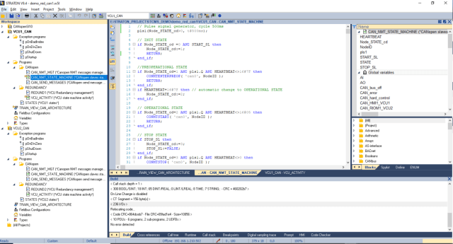
A list of projects is shown in the above workspace area: three projects are available and can be designed and debugged.
The project called “VCU1_CAN” is divided into several programs and tools to manage different features: Startup, VCU redundancy, CAN & CANopen communication.
VCU Redundancy
VCU redundancy is managed to enable a hot redundancy if one VCU fails. In each VCU, two programs manage the redundancy process:
- Redundancy management with the second VCU: “REDUND” program.
This program calls the function block “VCU_ACTIVITY”.
- VCU Activity State Machine: “VCU_ACTIVITY” function block.
This function block allows to calculate the VCU state: Start, Standby nominal, Standby degraded, Active nominal, Active degraded.

CAN & CANopen communication
CAN & CANopen communication is programmed through the Fieldbus configuration editor and structured programs:
Fieldbus configuration editor
All CAN & CANopen messages are configured through the STRATON Fieldbus configuration tool:

Data exchange and diagnostic/control variables can be defined for each CAN message.
CAN messages samples:
- CAN Message ID 1 and 2 are used for the VCU redundancy between VCU1 and VCU2; each VCU send a heartbeat and its VCU activity state: those values are used in the “REDUND” program to manage the VCU activity state.
- CAN Message ID 18A, 28A are TPDO messages received from CANopen slave number 10.
- CAN Message ID 20A, 30A are RPDO messages sent to CANopen slave number 10 only when the VCU is active and then set the message control variable, as the “CO_10_CD10A” variable for message ID 20A.
- CAN Message ID 70A is the heartbeat message sent by CANopen slave number 10.
Structured programs
Several programs have been developed to manage the messages defined in the fieldbus configuration editor:
- CANopen send messages management program: ”CAN_SEND_MESSAGES”. This program is used to trigger the sending of CANopen RPDO messages to CANopen slaves, only if the VCU is in an active state. The command variable for sending a CAN message is set in the CAN message (fieldbus configuration).
- CANopen NMT messages management: “REDUND” program. Only the active VCU will send NMT messages and manage the CANopen slaves. Call to a CANopen State Machine function block instance for each CANopen slave managed.
- CANopen State Machine function block: “CAN_NMT_STATE_MACHINE”. This function block allows to manage the CANopen states for a CANopen slave.
Monitoring view
For debugging the system, several STRATON tools are available: list of variables, graphic monitoring views, soft oscilloscope, test sequences, output window view, and digital sampling traces.
In a graphic monitoring view, all objects can be animated by the project variables’ values, when in simulation or online mode:

Tests
The three devices in the system were downloaded with their STRATON project from the project list.
All of those devices can be debugged at the same time through the STRATON workbench or in several STRATON workbench instances:

CAN communication can be monitored through the PC with a specific CAN network software: the tool used here is “Busmaster” software. An USB/CAN converter is used to connect the PC to the CAN network. All CAN messages and the bus load can be monitored.

The system process can be monitored through the STRATON graphic view:
AT A GLANCE :
- CAN and CANopen technologies save a lot of time in the design and implementation of a “real-time” system that must communicate in a network and where the quantity of data to be transmitted is limited.
- The supervision and communication mechanisms are provided, the hardware and software layers have proven their efficiency and robustness for many years.
- CANopen allows you to benefit from existing business profiles in order to make a device recognizable by a CANopen master, again saving development and integration time.
- An application written for a CANopen system, as well as CANopen hardware, can easily evolve to real-time Ethernet architectures like EtherCAT, because CANopen is supported by those protocols. Another proof of the maturity and effectiveness of this technology!
- Specific CANopen application profiles already exist for rolling stock and can be easily deployed on existing materials in case of retrofit, or on new projects, always with a cost optimization in mind.
CONCLUSION:
In conclusion, this press release has provided a comprehensive overview of the pivotal role that CAN (Controller Area Network) and CANopen technologies play within the realm of Train Control and Monitoring System (TCMS) for Railway Applications.
For those seeking more in-depth technical insights or wishing to delve into the intricacies of CAN and CANopen technologies within TCMS, Leroy Automation invites you to reach out.
For further technical details, or to receive the comprehensive application note, please contact Leroy Automation directly. Your inquiries are welcomed, and the Leroy Automation team is poised to provide expert guidance, ensuring you stay at the forefront of innovation in the ever-evolving world of railway control systems. Discover the future of rail technology with Leroy Automation – where excellence meets expertise.

